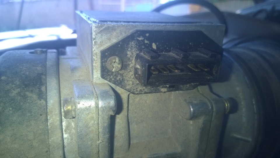
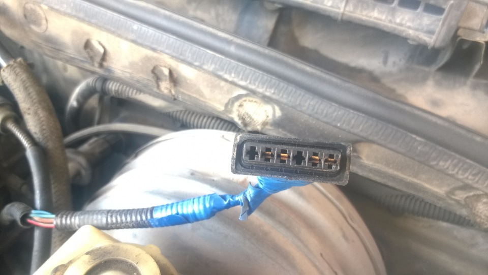
С разъёмом с одним хорошим электронщиком разобрались.Подсоединяется 4 контакта,нужно было разъём наоборот поставить,цифры на нём должны лежать снизу. А на плате ДМРВ он пару сгоревших сопротивлений и один транзистор поменял. Остаётся понять ДМРВ работает или нет? Вот буду благодарен,если найдёте где написано про проверку работоспособности ДМРВ на Диско,а то я кучу видео смотрел на ютюбе,там говориться про показания от 0.996 до 1.05,но у нас и мимо таких циферок не получается.
ПС. Интересную инфу нарыл Testing is performed in the following manner. Peel back the rubber boot on the airflow meter connector and leave it plugged in to the airflow meter. Set up the digital multimeter to read voltage. Insert the negative probe into the Red/Black wire (sensor ground), and the positive into the Blue/Green wire (Airflow signal).
Turn on the ignition, but do not start the engine. The meter should immediately indicate a reading of approximately 0.3-0.34 Volts. Most defective airflow meters will overshoot to 0.5 Volts or higher, and take at least 2 seconds to come down to the correct voltage.
Now start the engine, and the reading should rise to 1.6 Volts (3.5 Litre engine) to 1.75 Volts (5.0 Litre engine).
The next test is full load, and as with the fuel pressure test it will require use of a rolling road or a steep hill in the same manner. Under full load the voltage should rise to 4.45 Volts (3.5 Litre engine) to 4.95 Volts (5.0 Litre engine).
On this injection system, the idle CO mixture adjuster is provided on the airflow meter. It is located in a boss on the top of the airflow meter, pointing towards the engine. Leaving the multimeter negative probe in the Red/Black wire, move the positive probe to the Blue/Red wire.
Now turn on the ignition but do not start the engine. Observe the voltage. The normal adjustment range is between 0.0 and 3.6 Volts, with the higher Voltages producing higher idle CO values. There are approximately 20 turns of the adjuster screw to cover the entire range.
Annoyingly, the adjustment may be clockwise or anticlockwise to increase the value, and this varies from meter to meter! For this reason it is always preferable to have the multimeter connected in this manner when adjusting idle CO, so that you see can something is actually happening.
Typical Voltages that would be found at this point are between 0.9 to 1.4 Volts for non-catalyst cars. This Voltage is always factory pre-set to 1.8 Volts for catalyst vehicles. A value near to 3.5 Volts will generally produce an idle CO value of 9-10%. These Voltages may be used as safe initial values particularly if no CO measuring equipment is available